EnviroPressure®
Enviropipes manufacture EnviroPressure® pressure pipes in Australia up to 1600mm in diameter. All EnviroPressure® pipes are WaterMark certified and WSAA appraised to AS/NZS 4130:2018.
Contact Sales
Overview
All pressure pipes are made from virgin PIPA approved raw materials and the range includes black, black with internal or external-coloured HDPE jackets or striped pipes for water or gas supply and distribution up to 3000kPa operating pressure and up to a maximum service temperature of 80°C.
Applications
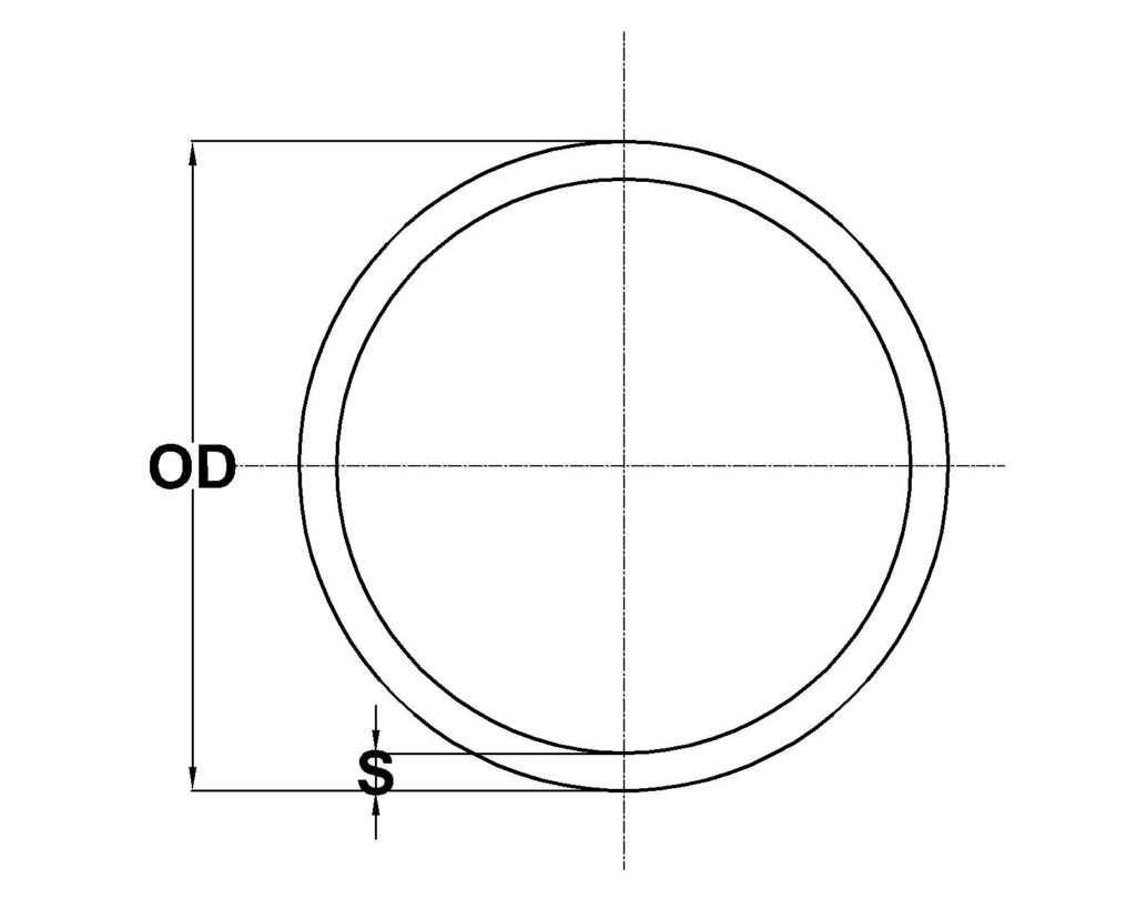
Dimensions
Pipe pressure rating is based upon wall thicknesses of PE100 High Density Polyethylene as follows. Pipes can be delivered in straight lengths or up to 400 metre coiled lengths to ease underground installations, or to suit your design or transport requirements.
SDR41 and SDR26 PE100 High Density Polyethylene Pressure Pipe to AS4130
| OD | SDR41 PN4 | SDR26 PN6.3 | ||||
|---|---|---|---|---|---|---|
| S | ID | Kg/m | S | ID | Kg/m | |
| 25 | – | – | – | – | – | – |
| 32 | – | – | – | – | – | – |
| 40 | – | – | – | – | – | – |
| 50 | – | – | – | – | – | – |
| 63 | – | – | – | 2.6 | 57.9 | 0.47 |
| 75 | – | – | – | 3.1 | 68.9 | 0.66 |
| 90 | – | – | – | 3.7 | 82.7 | 0.96 |
| 110 | 2.8 | 104.3 | 0.92 | 4.5 | 101.0 | 1.43 |
| 125 | 3.2 | 118.5 | 1.19 | 5.1 | 114.8 | 1.84 |
| 140 | 3.6 | 132.8 | 1.49 | 5.7 | 128.6 | 2.31 |
| 160 | 4.1 | 151.7 | 1.94 | 6.5 | 147.0 | 3.02 |
| 180 | 4.7 | 170.7 | 2.46 | 7.3 | 165.3 | 3.82 |
| 200 | 5.2 | 189.7 | 3.04 | 8.2 | 183.7 | 4.72 |
| 225 | 5.8 | 213.4 | 3.85 | 9.2 | 206.7 | 5.97 |
| 250 | 6.5 | 237.1 | 4.75 | 10.2 | 229.6 | 7.37 |
| 280 | 7.2 | 265.5 | 5.96 | 11.4 | 257.2 | 9.25 |
| 315 | 8.1 | 298.7 | 7.54 | 12.8 | 289.3 | 11.70 |
| 355 | 9.2 | 336.6 | 9.57 | 14.5 | 326.1 | 14.86 |
| 400 | 10.3 | 379.3 | 12.15 | 16.3 | 367.4 | 18.87 |
| 450 | 11.6 | 426.7 | 15.38 | 18.3 | 413.3 | 23.88 |
| 500 | 12.9 | 474.1 | 18.99 | 20.4 | 459.2 | 29.49 |
| 560 | 14.5 | 531.0 | 23.82 | 22.8 | 514.3 | 36.99 |
| 630 | 16.3 | 597.4 | 30.15 | 25.7 | 578.6 | 46.81 |
| 710 | 18.4 | 673.3 | 38.29 | 28.9 | 652.1 | 59.46 |
| 800 | 20.7 | 758.6 | 48.61 | 32.6 | 734.8 | 75.48 |
| 900 | 23.3 | 853.5 | 61.53 | 36.7 | 826.6 | 95.54 |
| 1000 | 25.9 | 948.3 | 75.96 | 40.8 | 918.5 | 117.94 |
| 1200 | 31.0 | 1138.0 | 109.38 | 48.9 | 1102.2 | 169.84 |
| 1400 | 36.2 | 1327.6 | 148.88 | 57.1 | 1285.8 | 231.17 |
| 1600 | 41.4 | 1517.3 | 194.45 | 65.2 | 1469.5 | 301.94 |
| 1800 | 46.5 | 1706.9 | 246.10 | 73.4 | 1653.2 | 38214 |
| 2000 | 51.7 | 1896.6 | 303.83 | 81.5 | 1836.9 | 471.78 |
SDR21 AND SDR17 PE100 High Density Polyethylene Pressure Pipe to AS4130
| OD | SDR21 PN8 | SDR17 PN10 | ||||
|---|---|---|---|---|---|---|
| S | ID | Kg/m | S | ID | Kg/m | |
| 25 | – | – | – | – | – | – |
| 32 | – | – | – | 2.0 | 28.0 | 0.18 |
| 40 | 2.0 | 36.0 | 0.23 | 2.5 | 35.0 | 0.28 |
| 50 | 2.5 | 45.0 | 0.36 | 3.1 | 43.8 | 0.44 |
| 63 | 3.2 | 56.6 | 0.57 | 3.9 | 55.1 | 0.70 |
| 75 | 3.8 | 67.4 | 0.81 | 4.7 | 65.6 | 0.99 |
| 90 | 4.5 | 80.9 | 1.17 | 5.6 | 78.8 | 1.43 |
| 110 | 5.6 | 98.9 | 1.75 | 6.9 | 96.3 | 2.13 |
| 125 | 6.3 | 112.4 | 2.26 | 7.8 | 109.4 | 2.76 |
| 140 | 7.1 | 125.9 | 2.83 | 8.7 | 122.5 | 3.46 |
| 160 | 8.1 | 143.8 | 3.70 | 10.1 | 140.0 | 4.51 |
| 180 | 9.1 | 161.8 | 4.68 | 11.2 | 157.6 | 5.71 |
| 200 | 10.1 | 179.8 | 5.78 | 12.5 | 175.1 | 7.05 |
| 225 | 11.4 | 202.3 | 7.32 | 14.0 | 196.9 | 8.93 |
| 250 | 12.6 | 224.8 | 9.03 | 15.6 | 218.8 | 11.02 |
| 280 | 14.1 | 251.7 | 11.33 | 17.5 | 245.1 | 13.82 |
| 315 | 15.9 | 283.2 | 14.34 | 19.6 | 275.7 | 17.50 |
| 355 | 17.9 | 319.2 | 18.22 | 22.1 | 310.7 | 22.22 |
| 400 | 20.2 | 359.6 | 23.13 | 24.9 | 350.1 | 28.21 |
| 450 | 22.7 | 404.6 | 29.27 | 28.1 | 393.9 | 35.71 |
| 500 | 25.2 | 449.5 | 36.14 | 31.2 | 437.6 | 44.08 |
| 560 | 28.3 | 503.5 | 45.33 | 34.9 | 490.2 | 55.30 |
| 630 | 31.8 | 566.4 | 57.37 | 39.3 | 551.4 | 69.98 |
| 710 | 35.8 | 638.3 | 72.87 | 44.3 | 621.5 | 88.89 |
| 800 | 40.4 | 719.2 | 92.51 | 49.9 | 700.2 | 112.85 |
| 900 | 45.4 | 809.1 | 117.08 | 56.1 | 787.8 | 142.82 |
| 1000 | 50.5 | 899.0 | 144.55 | 62.4 | 875.3 | 176.33 |
| 1200 | 60.6 | 1078.9 | 208.15 | 74.8 | 1050.4 | 253.91 |
| 1400 | 70.7 | 1258.7 | 283.32 | 87.3 | 1225.4 | 345.60 |
| 1600 | 80.8 | 1438.5 | 370.04 | 99.8 | 1400.5 | 451.40 |
| 1800 | 90.9 | 1618.3 | 468.34 | 112.2 | 1575.5 | 571.30 |
| 2000 | 101.0 | 1798.1 | 578.20 | 124.7 | 1750.6 | 705.31 |
SDR13.6 and SDR11 PE100 High Density Polyethylene Pressure Pipe to AS4130
| OD | SDR13.6 PN12.5 | SDR11 PN16 | ||||
|---|---|---|---|---|---|---|
| S | ID | Kg/m | S | ID | Kg/m | |
| 25 | 1.9 | 21.1 | 0.14 | 2.4 | 20.2 | 0.16 |
| 32 | 2.5 | 27.0 | 0.22 | 3.1 | 25.8 | 0.27 |
| 40 | 3.1 | 33.8 | 0.35 | 3.9 | 32.3 | 0.42 |
| 50 | 3.9 | 42.2 | 0.54 | 4.8 | 40.4 | 0.66 |
| 63 | 4.9 | 53.2 | 0.86 | 6.1 | 50.9 | 1.04 |
| 75 | 5.8 | 63.3 | 1.22 | 7.2 | 60.5 | 1.48 |
| 90 | 7.0 | 76.0 | 1.76 | 8.7 | 72.7 | 2.13 |
| 110 | 8.6 | 92.9 | 2.62 | 10.6 | 88.8 | 3.18 |
| 125 | 9.7 | 105.5 | 3.39 | 12.0 | 100.9 | 4.10 |
| 140 | 10.9 | 118.2 | 4.25 | 13.5 | 113.0 | 5.15 |
| 160 | 12.5 | 135.1 | 5.55 | 15.4 | 129.2 | 6.72 |
| 180 | 14.0 | 151.9 | 7.02 | 17.3 | 145.3 | 8.51 |
| 200 | 15.6 | 168.8 | 8.67 | 19.3 | 161.5 | 10.50 |
| 225 | 17.5 | 189.9 | 10.97 | 21.7 | 181.6 | 13.30 |
| 250 | 19.5 | 211.0 | 13.55 | 24.1 | 201.8 | 16.41 |
| 280 | 21.8 | 236.4 | 16.99 | 27.0 | 226.0 | 20.59 |
| 315 | 24.6 | 265.9 | 21.51 | 30.4 | 254.3 | 26.06 |
| 355 | 27.7 | 299.7 | 27.32 | 34.2 | 286.6 | 33.10 |
| 400 | 31.2 | 339.6 | 34.68 | 38.5 | 322.9 | 42.02 |
| 450 | 35.1 | 379.9 | 43.89 | 43.4 | 363.3 | 53.18 |
| 500 | 39.0 | 422.1 | 54.19 | 48.2 | 403.6 | 65.66 |
| 560 | 43.6 | 472.7 | 67.97 | 54.0 | 452.1 | 82.36 |
| 630 | 49.1 | 531.8 | 86.03 | 60.7 | 508.6 | 104.23 |
| 710 | 55.3 | 599.3 | 109.26 | 68.4 | 573.2 | 132.39 |
| 800 | 62.4 | 675.3 | 138.72 | 77.1 | 645.8 | 168.08 |
| 900 | 70.1 | 759.7 | 175.56 | 86.7 | 726.5 | 212.72 |
| 1000 | 77.9 | 844.1 | 216.74 | 96.4 | 807.3 | 262.62 |
| 1200 | 93.5 | 1012.9 | 312.11 | 115.6 | 968.7 | 378.17 |
| 1400 | 109.1 | 1181.8 | 424.82 | 134.9 | 1130.2 | 514.74 |
| 1600 | 124.7 | 1350.6 | 554.87 | – | – | – |
| 1800 | 140.3 | 1519.4 | 702.25 | – | – | – |
| 2000 | 155.9 | 1688.2 | 866.98 | – | – | – |
SDR9 and SDR7.4 PE100 High Density Polyethylene Pressure Pipe to AS4130
| OD | SDR9 PN20 | SDR7.4 PN25 | ||||
|---|---|---|---|---|---|---|
| S | ID | Kg/m | S | ID | Kg/m | |
| 25 | 2.9 | 19.1 | 0.20 | 3.6 | 17.8 | 0.23 |
| 32 | 3.8 | 24.5 | 0.32 | 4.6 | 22.8 | 0.38 |
| 40 | 4.7 | 30.6 | 0.50 | 5.7 | 28.5 | 0.59 |
| 50 | 5.9 | 38.2 | 0.78 | 7.2 | 35.7 | 0.93 |
| 63 | 7.4 | 48.2 | 1.24 | 9.0 | 45.0 | 1.47 |
| 75 | 8.8 | 57.3 | 1.76 | 10.7 | 53.5 | 2.08 |
| 90 | 10.6 | 68.8 | 2.54 | 12.9 | 64.2 | 3.00 |
| 110 | 13.0 | 84.1 | 3.79 | 15.8 | 78.5 | 4.48 |
| 125 | 14.7 | 95.6 | 4.90 | 17.9 | 89.2 | 5.78 |
| 140 | 16.5 | 107.0 | 6.14 | 20.1 | 99.9 | 7.25 |
| 160 | 18.8 | 122.3 | 8.02 | 22.9 | 114.2 | 9.48 |
| 180 | 21.2 | 137.6 | 10.15 | 25.8 | 128.4 | 11.99 |
| 200 | 23.6 | 152.9 | 12.53 | 28.6 | 142.7 | 14.81 |
| 225 | 26.5 | 172.0 | 15.86 | 32.2 | 160.5 | 18.74 |
| 250 | 29.4 | 191.1 | 19.59 | 35.8 | 178.4 | 23.13 |
| 280 | 33.0 | 214.0 | 24.57 | 40.1 | 199.8 | 29.02 |
| 315 | 37.1 | 240.8 | 31.09 | 45.1 | 224.8 | 36.73 |
| 355 | 41.8 | 271.4 | 39.49 | 50.9 | 253.3 | 46.65 |
| 400 | 47.1 | 305.8 | 50.14 | 57.3 | 285.4 | 59.22 |
| 450 | 53.0 | 344.0 | 63.46 | 64.5 | 321.1 | 74.95 |
| 500 | 58.9 | 382.2 | 78.34 | 71.6 | 356.8 | 92.53 |
| 560 | 66.0 | 428.1 | 98.27 | 80.2 | 399.6 | 116.07 |
| 630 | 74.2 | 481.6 | 124.38 | 90.2 | 449.5 | 146.90 |
| 710 | 83.6 | 542.8 | 157.97 | 101.7 | 506.5 | 186.58 |
| 800 | 94.2 | 611.6 | 200.56 | – | – | – |
| 900 | – | – | – | – | – | – |
| 1000 | – | – | – | – | – | – |
| 1200 | – | – | – | – | – | – |
| 1400 | – | – | – | – | – | – |
| 1600 | – | – | – | – | – | – |
| 1800 | – | – | – | – | – | – |
| 2000 | – | – | – | – | – | – |
…
Technical
Effects of Temperature on Allowable Working Pressure
As the temperature of the wall of the Pressure pipe increases, the working pressure must be reduced in order to achieve a 50 year life (or as stated in parenthesis), as per the following table:
Pressure re-rating due to thermal effects maximum allowable operating pressure (MAOP), meters head – PE100.
| Temp °C | PN 4 | PN 6.3 | PN 8 | PN 10 | PN 12.5 | PN 16 | PN 20 | PN 25 |
|---|---|---|---|---|---|---|---|---|
| 20 | 40 | 63 | 80 | 100 | 125 | 160 | 200 | 250 |
| 25 | 40 | 63 | 80 | 100 | 125 | 160 | 200 | 250 |
| 30 | 38 | 59 | 75 | 94 | 118 | 150 | 188 | 235 |
| 35 | 36 | 56 | 71 | 89 | 116 | 143 | 179 | 224 |
| 40 | 34 | 53 | 68 | 84 | 106 | 135 | 169 | 221 |
| 45 | 32 | 50 | 64 | 80 | 100 | 127 | 159 | 199 |
| 50 (36y) | 30 | 48 | 60 | 76 | 95 | 121 | 151 | 189 |
| 55 (24y) | 29 | 45 | 57 | 72 | 89 | 115 | 143 | 179 |
| 60 (12y) | 27 | 43 | 54 | 68 | 85 | 109 | 136 | 170 |
| 80 (1y) | 21 | 34 | 43 | 53 | 67 | 86 | 107 | 134 |
Note:
- The values tabled are for pipe manufactured to AS/NZS 4130 and fittings manufactured to AS/NZS 4129 made from the PE100 compounds complying with AS/NZS 4131.
- The values tabled are only for pressurised water and wastewater supply pipe and fittings. For the transport of liquid chemicals please refer to the Chemical Resistance Charts in the Catalogue.
- The times given in years as (36y) are allowable extrapolation limits obtained by applying the factors in table 1 of ISO 9080 to two years of test data at 80°C.
- Where appropriate, advice should be obtained from Enviropipes. Enviropipes can supply white coextruded pipe, which has an external UV resistant HDPE layer, reducing the wall temperatures for above ground pipelines in hot climates due to solar radiation absorption.
Operating pipe wall temperature may be determined from either:
- an assumption of a constant pipe wall temperature typical for continuous service at a set temperature.
- the determination of an average service temperature where temperature variations are likely to occur in a predictable pattern.
- the maximum service temperature less 10°C for installations where large short term temperature variations occur up to a maximum of 80°C.
The table above applies to water or wastewater supply only.
For the transport of liquid chemicals please refer to the Chemical Resistance Charts in the Catalogue. The maximum and minimum temperatures allowed for the pipe material is based on the service (see below). Enviropipes can supply white coextruded pipe, which has an external UV resistant HDPE layer, reducing the wall temperatures for above ground pipelines in hot climates due to solar radiation absorption.
| Service | Applicable Standard | Minimum Temperature (PE100) | Maximum Temperature (PE100) |
|---|---|---|---|
| Fuel Gas | AS 4645.3 | -10°C | 40°C |
| Water | AS/NZS 4130 | In excess of -20°C | 80°C |
| Air | PIPA POP002 | -20°C | 60°C |
Support Spans for Horizontal Pipes
The following table is suggested support spans in metres, for above ground pipes to limit a pipe’s vertical deflection to 200 times less than the span between supports.
The following assumptions have been made to enable the calculations.
- Pipe is not under pressure and is full of water.
- Design life is for 100 years
- Average temperature of the pipe wall is a constant, at a maximum 40°C
- Pipe supports allow the pipe to move axially.
- No thermal expansion effects considered.
- No external earthquake, wind or live loads applied to the pipe.
- Pipe is laid horizontally.
| OD | SDR 41 | SDR 26 | SDR 21 | SDR 17 | SDR 13.6 | SDR 11 | SDR 9 | SDR 7.4 |
|---|---|---|---|---|---|---|---|---|
| 16 | – | – | – | – | – | 0.60 | 0.60 | 0.60 |
| 20 | – | – | – | 0.60 | 0.73 | 0.70 | 0.70 | 0.70 |
| 25 | – | – | 0.57 | 0.70 | 0.83 | 0.75 | 0.75 | 0.75 |
| 32 | – | 0.55 | 0.67 | 0.80 | 0.93 | 0.85 | 0.85 | 0.85 |
| 40 | 0.54 | 0.65 | 0.77 | 0.90 | 1.03 | 0.90 | 0.90 | 0.90 |
| 50 | 0.64 | 0.75 | 0.87 | 1.00 | 1.13 | 1.05 | 1.05 | 1.05 |
| 63 | 0.74 | 0.85 | 0.97 | 1.10 | 1.23 | 1.10 | 1.10 | 1.10 |
| 75 | 0.84 | 0.95 | 1.07 | 1.20 | 1.33 | 1.30 | 1.30 | 1.30 |
| 90 | 0.94 | 1.05 | 1.17 | 1.30 | 1.43 | 1.40 | 1.40 | 1.40 |
| 110 | 1.04 | 1.15 | 1.27 | 1.40 | 1.53 | 1.50 | 1.50 | 1.50 |
| 125 | 1.14 | 1.25 | 1.37 | 1.50 | 1.63 | 1.70 | 1.70 | 1.70 |
| 140 | 1.24 | 1.35 | 1.47 | 1.60 | 1.73 | 1.70 | 1.70 | 1.70 |
| 160 | 1.34 | 1.45 | 1.57 | 1.70 | 1.83 | 2.00 | 2.00 | 2.00 |
| 180 | 1.44 | 1.55 | 1.67 | 1.80 | 1.93 | 2.08 | 2.23 | 2.40 |
| 200 | 1.56 | 1.68 | 1.81 | 1.94 | 2.09 | 2.25 | 2.42 | 2.60 |
| 225 | 1.68 | 1.81 | 1.95 | 2.09 | 2.25 | 2.42 | 2.60 | 2.80 |
| 250 | 1.81 | 1.94 | 2.09 | 2.24 | 2.41 | 2.59 | 2.79 | 3.00 |
| 280 | 1.93 | 2.07 | 2.23 | 2.39 | 2.57 | 2.77 | 2.98 | 3.20 |
| 315 | 2.11 | 2.26 | 2.43 | 2.62 | 2.82 | 3.03 | 3.26 | 3.50 |
| 355 | 2.29 | 2.46 | 2.64 | 2.84 | 3.06 | 3.29 | 3.53 | 3.80 |
| 400 | 2.47 | 2.65 | 2.85 | 3.07 | 3.30 | 3.55 | 3.81 | 4.10 |
| 450 | 2.71 | 2.91 | 3.13 | 3.37 | 3.62 | 3.89 | 4.19 | 4.50 |
| 500 | 2.89 | 3.11 | 3.34 | 3.59 | 3.86 | 4.15 | 4.46 | 4.80 |
| 560 | 3.13 | 3.36 | 3.62 | 3.89 | 4.18 | 4.50 | 4.84 | 5.20 |
| 630 | 3.57 | 3.79 | 4.04 | 4.29 | 4.57 | 4.86 | 5.17 | 5.50 |
| 710 | 3.89 | 4.14 | 4.40 | 4.68 | 4.98 | 5.30 | 5.64 | 6.00 |
| 800 | 4.28 | 4.55 | 4.84 | 5.15 | 5.48 | 5.83 | 6.20 | 6.60 |
| 900 | 4.47 | 4.76 | 5.06 | 5.39 | 5.73 | 6.10 | 6.49 | 6.90 |
| 1000 | 4.86 | 5.17 | 5.50 | 5.86 | 6.23 | 6.63 | 7.05 | 7.50 |
Expansion and Contraction
Due to temperature effects and the Poisson effect, a HDPE pipe material will apply a stress which can be relieved by allowing the pipeline to move. Allowance for movement can be achieved by installing expansion joints, or by snaking a pipeline above ground.
Mitigation of thermal effects can be achieved by:
- Using pipe with an external co-extruded white outer HDPE layer to reduce temperature of the pipe due to solar radiation absorption.
- Burying a pipe as it is laid to prevent day/night temperature variation effects during construction.
Nomograms
Enviropipes Solid Walled Pipe Namograms in the following links and are based upon the Colebrook-White equation. Conditions to using these diagrams:
- This diagram is based upon clean fresh water flow at 20°C in full pipes.
- Darcy friction factor coefficient for clean HDPE is 0.015.
- Effects of entrance, exit losses, bends, pits, and junctions excluded from the analysis.
- For flow velocities below 0.5m/s or above 3m/s, local authority approval may be required.
- Maximum flow velocities above 0.5m/s encourages the self cleaning ability of the pipe, reducing the likelihood of silt deposits.
- The head loss does not include the effects of gravity (ie any changes in elevation)
Certifications
-
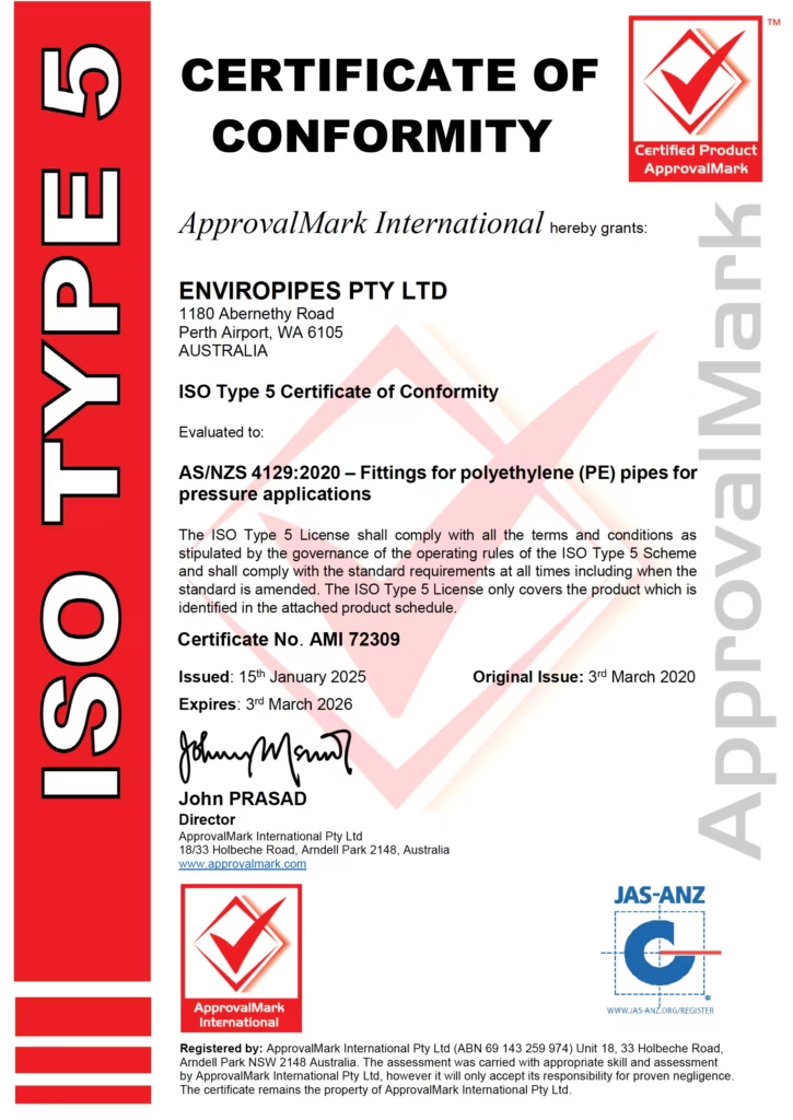
AS/NZS 4129:2020
-
AS/NZS 4130:2020
-
AS/NZS 5065:2005